One evening back in January I finally had enough of thermal issues within my homelab server. You know, every time the computer fans make more noise than I think they should, I can’t help but investigate!
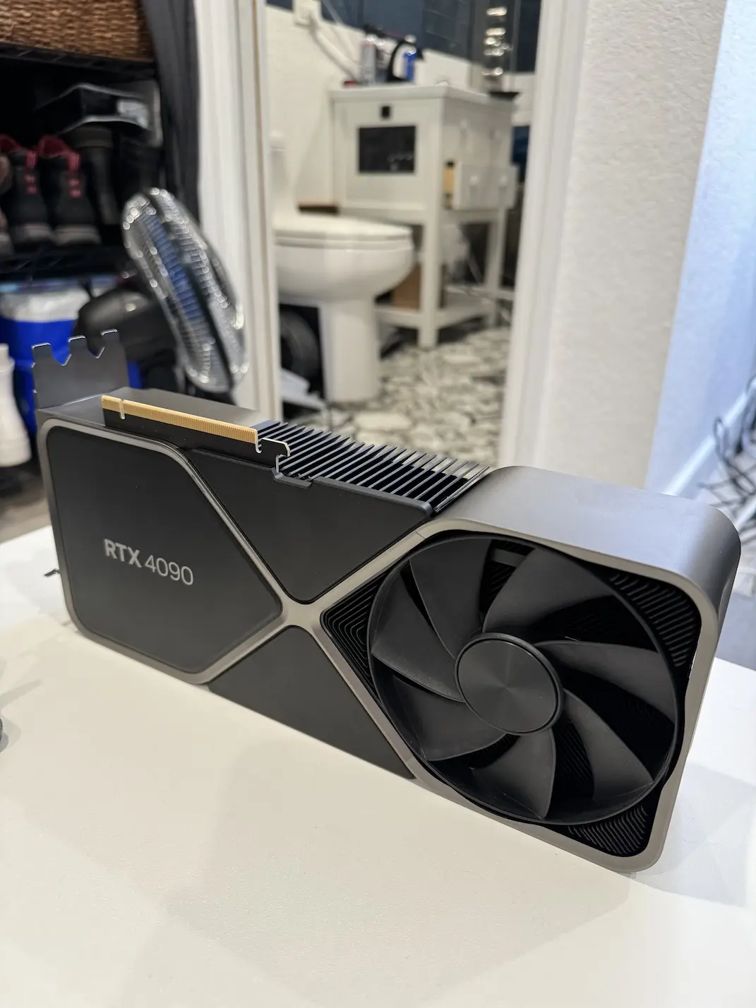
Also, the RTX4090 is so thick that it takes 3 PCIe slots worth of space on a typical motherboard - and you also need space for the airflow! I was using the same machine that achieved 11M IOPS & 66 GB/s IO on a Single ThreadRipper Workstation back in 2020. However, I had to take out most of the SSDs and the (also hot) 200Gbe Mellanox network card to fit the GPU in there. Lots of good hardware ended up sitting unused… Enough is enough, this has to stop!
It was in the middle of the night when I decided (realized?) that had to put everything else on hold and move the GPU outside of the chassis to get some peace again, so I set out to work with the tools I had and any leftovers from my other projects, plus possibly improvise with random household items. This is that story.
I have written comments below the images, so as you scroll down, you can first check out the photos and I’ll explain any context below. You can click on the photos to enlarge them.
The Starting Point
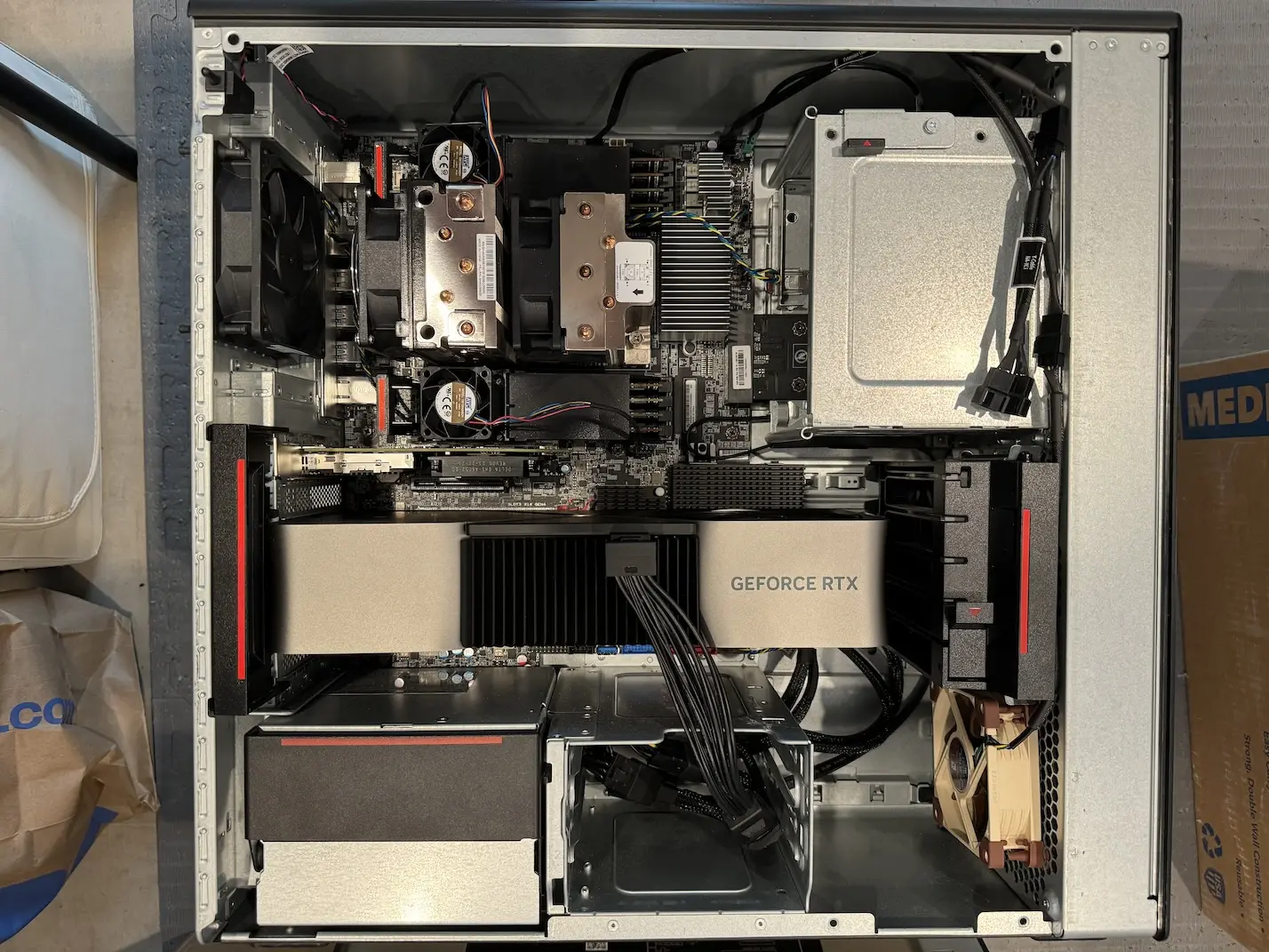
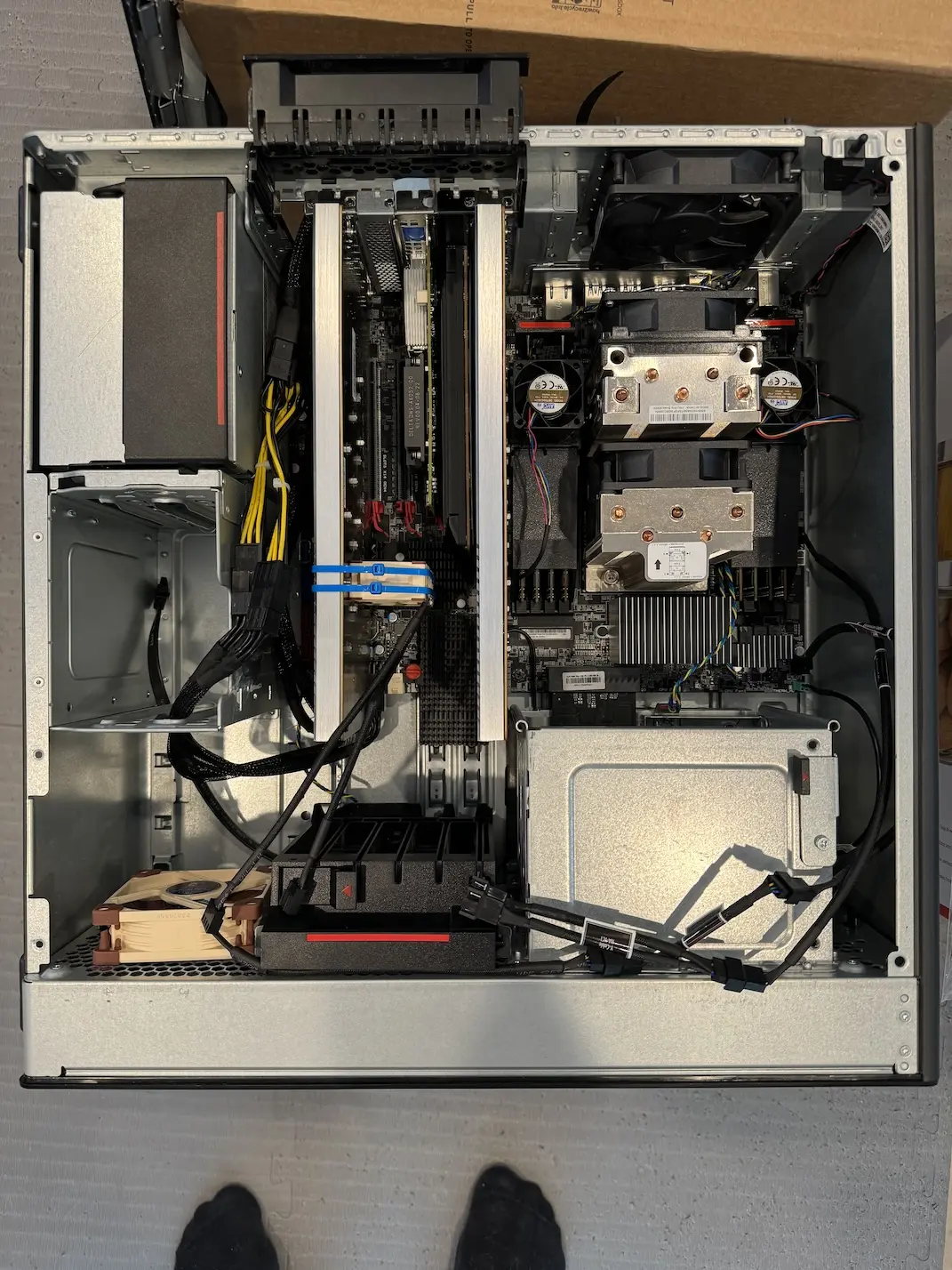
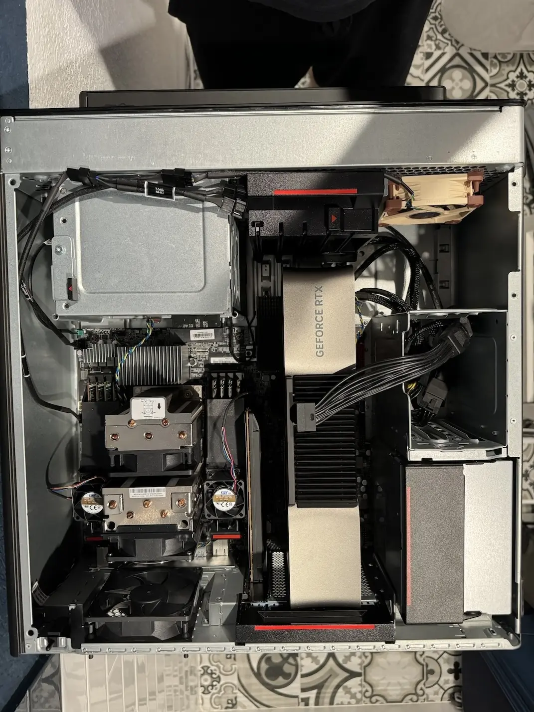
As you can see, the RTX 4090 takes almost all the space meant for PCI slots and there’s not that much room for proper airflow (for the given consumer type of a GPU). The GPU uses only one PCIe 4.0 x16 slot, but it blocks two others due to its size and you really don’t want to install any cards right in front of its fans either.
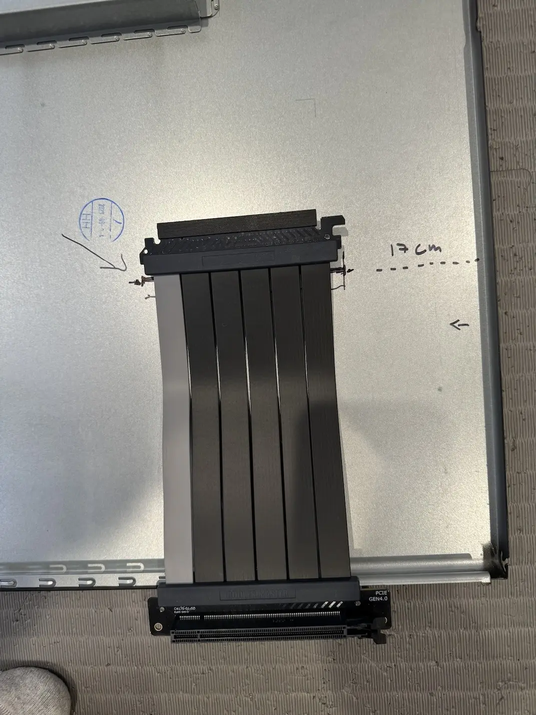
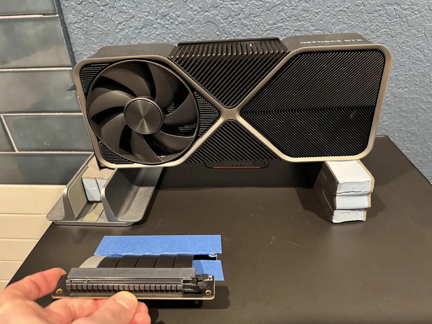
My idea was to just lift the GPU out from the chassis and be done with it. There’s plenty of space outside the machine and the airflow exhaust/intake capability is great! The key part that made this plan immediately possible is that I happened to have a PCIe4.0 extender cable available from a previous experiment with a PCIe riser frame (for a “vertical” GPU setup) on a different machine.
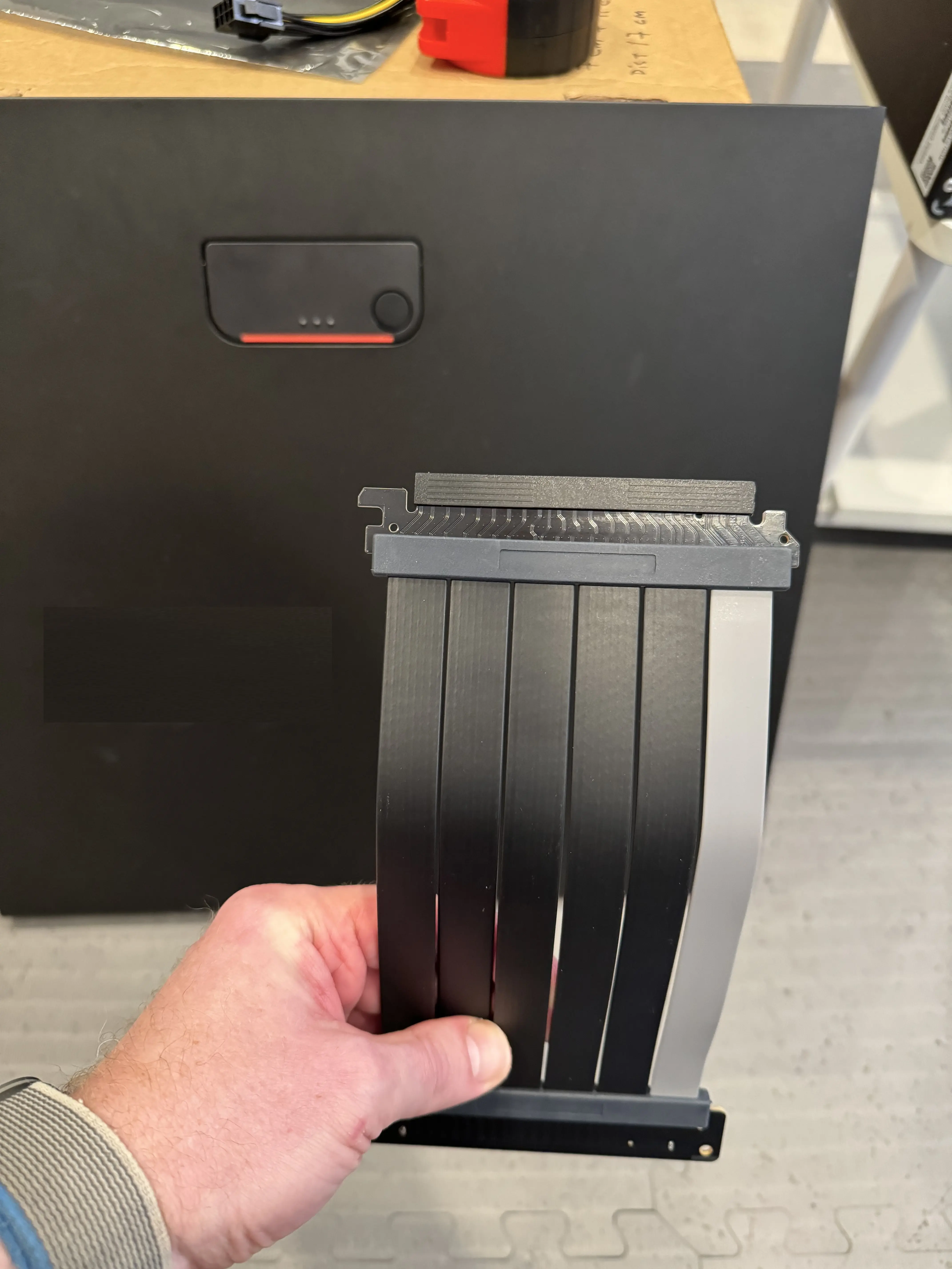
So I had the PCIe extender cable (PCIe 4.0-capable) and now I needed to make a big enough hole in the Thinkstation’s metal side panel.

The hole has to be in the right place of course and long & wide enough, as you can’t twist and turn that flat wide PCIe extender cable much. The cable is not that long anyway because of physics & signal quality. After all, the riser cable is just a few strings of copper, without any PCIe switches, retimers or redrivers.
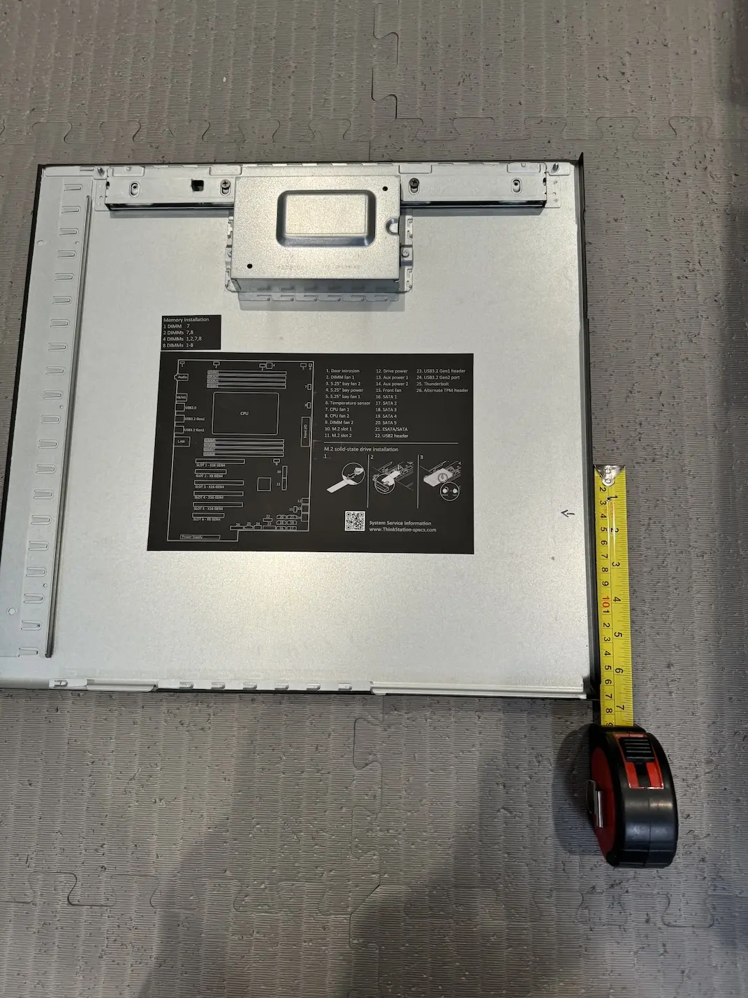
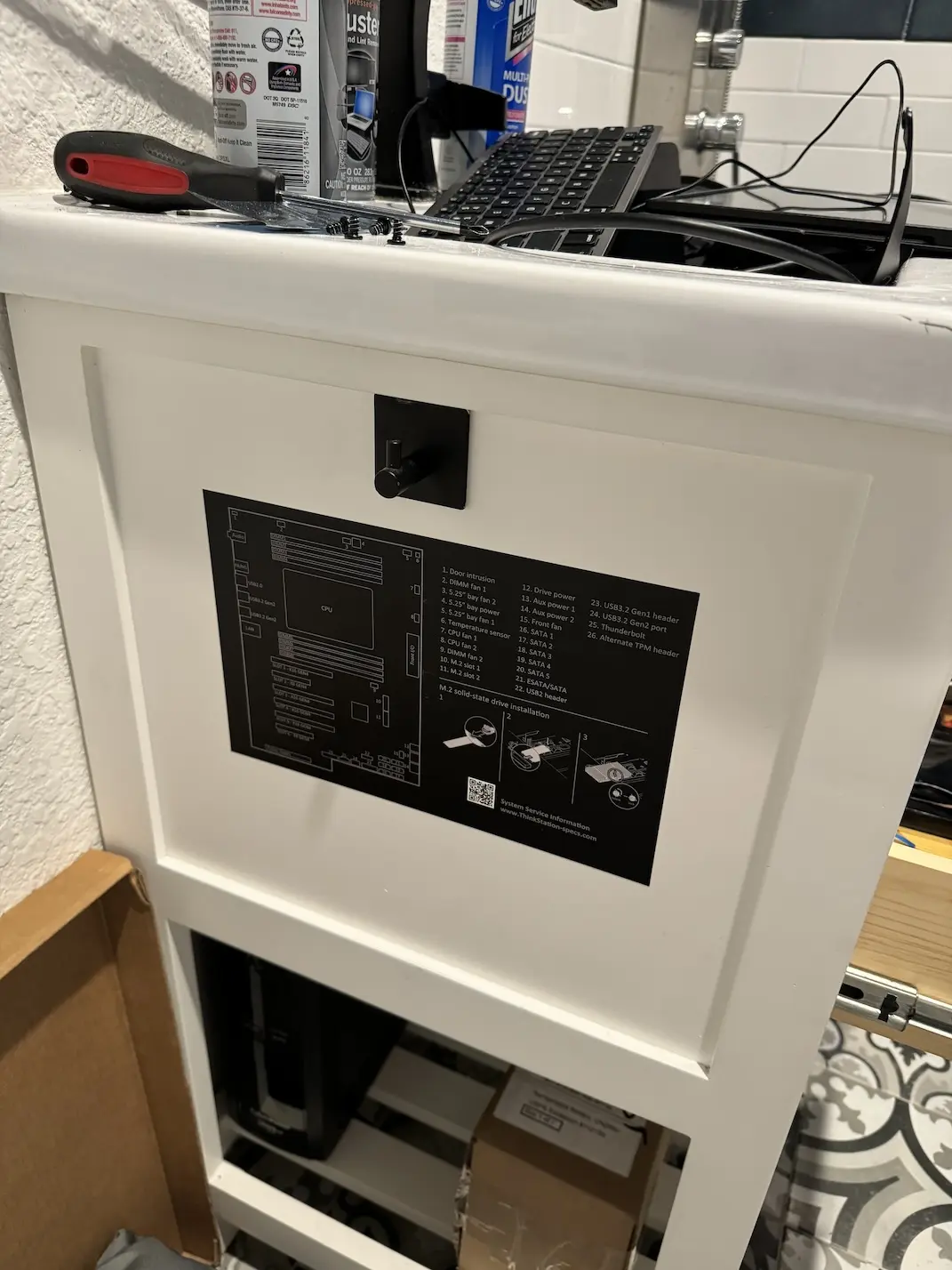
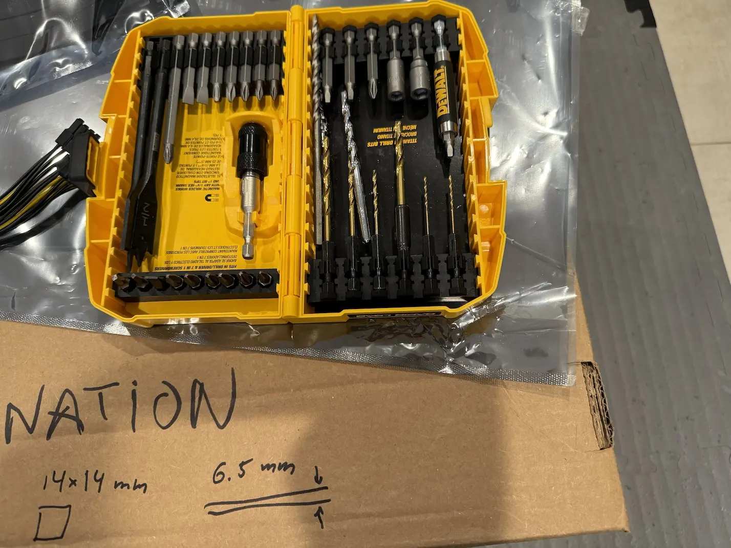
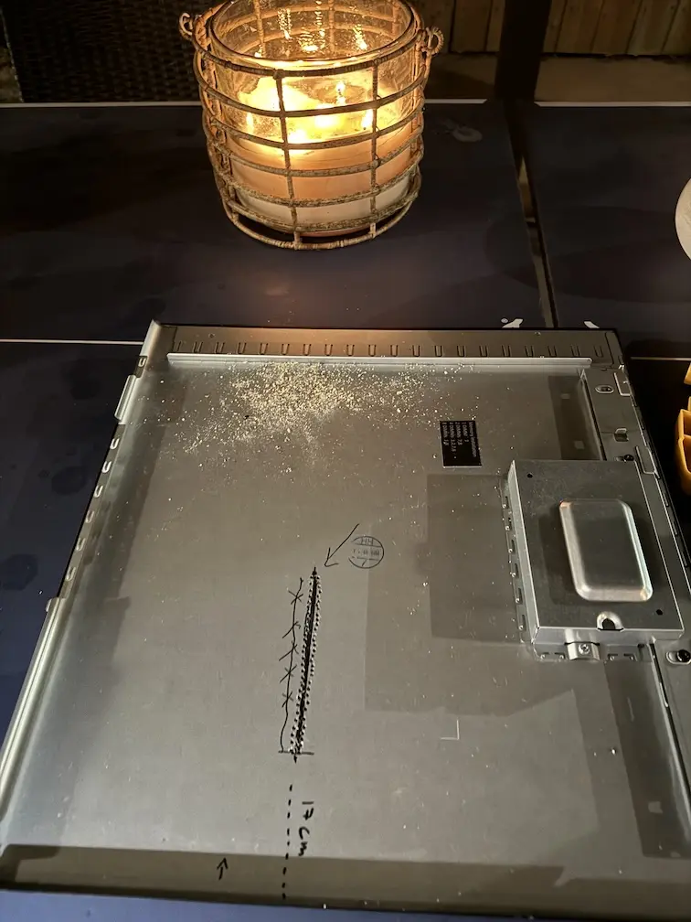
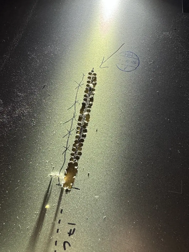
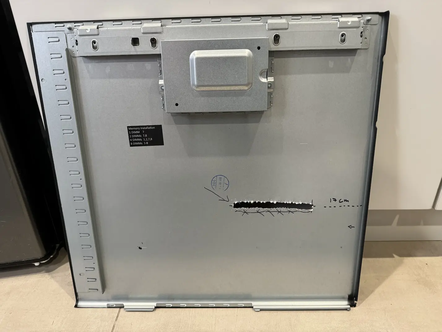
I wanted to do this right, so first I removed the Lenovo motherboard diagram sticker from the panel and took some measurements of where the GPU’s PCIe slot would be. The motherboard sticker found a nice new home on the side of my server room sink (!) in case of any… emergencies.
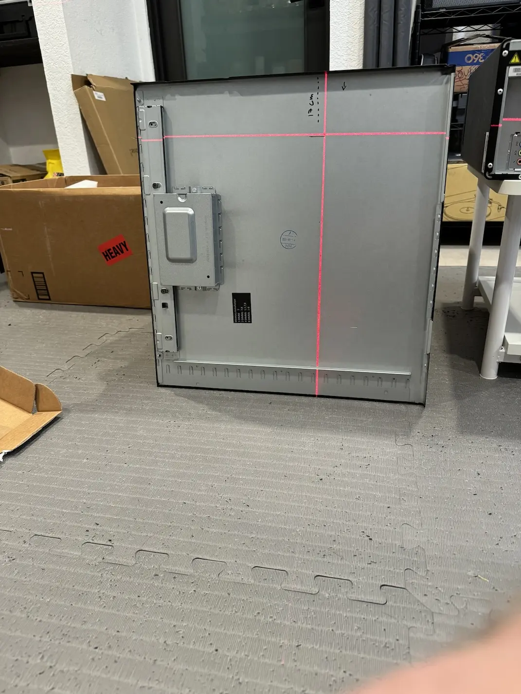
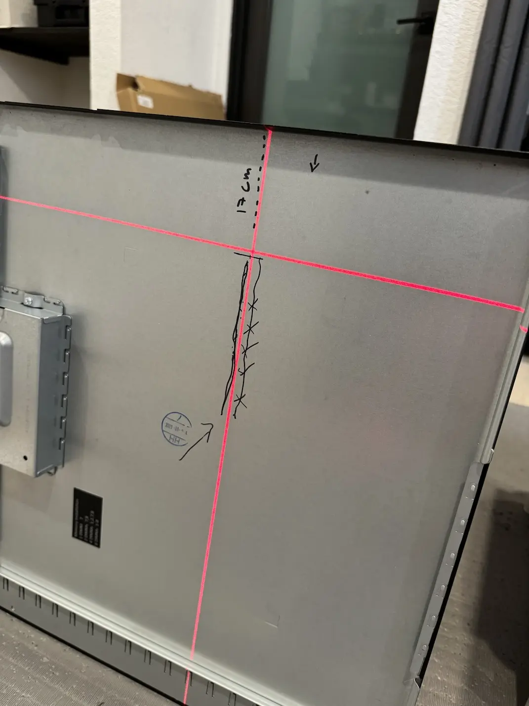
The above step is mandatory only if you already have laser level handy, otherwise just wing it. I did have one (or… whom am I kidding, I have two), so I tried to make sure that I wouldn’t cut the hole at some weird angle. In the middle photo above you see one of the marker lines being crossed out, that’s what you get when trying to draw a free-form straight line while not paying proper attention to the task at hand. So I crossed it out and the next marker line was better. I should’ve really used a ruler for directional stability, but I didn’t have one handy.
I also checked if the markings were wide/long enough as the PCIe connector itself is slightly wider than the cable.
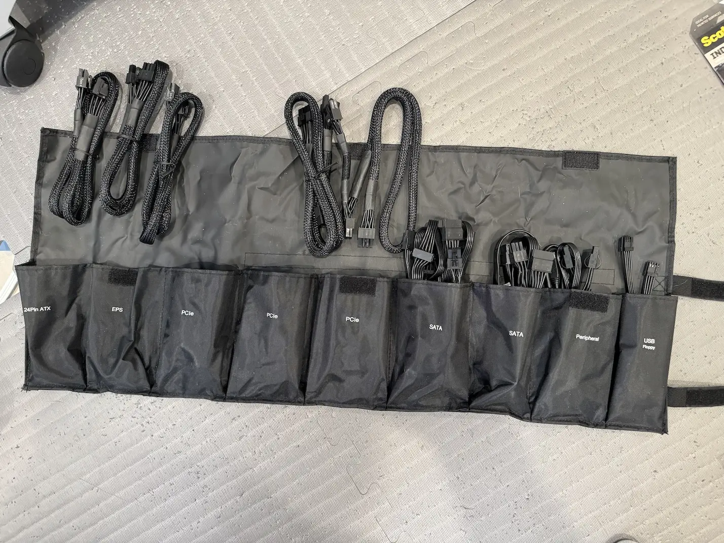
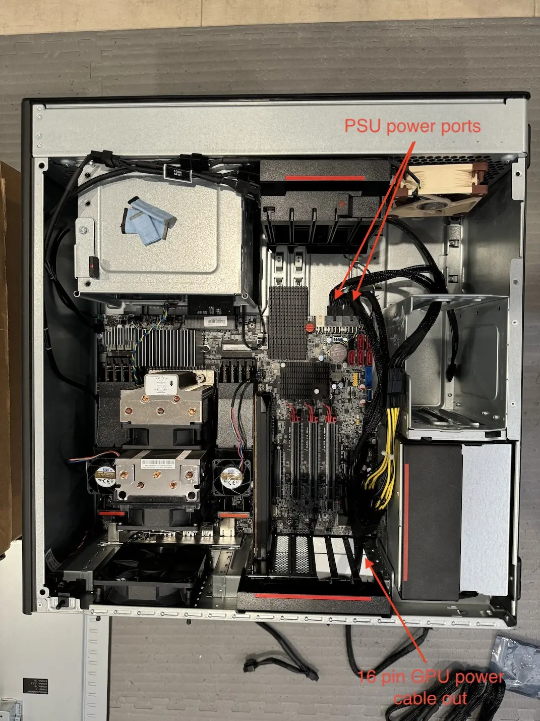
Next, I had to check if I even had a long enough power cable for feeding the GPU with its 450W power requirement. Actually, I needed 2 cables to connect to the PSU outputs, and both with splitters as the 12-pin 4090 power cable has 4 separate power inputs. Lenovo Thinkstation P620 supports 2x300W that way, so even though the RTX 4090 is not listed as a supported GPU, at least its power draw should not melt down things. 1
I had plenty of various power cables left from my christmas dual socket EPYC Genoa build, will talk about that some other day.
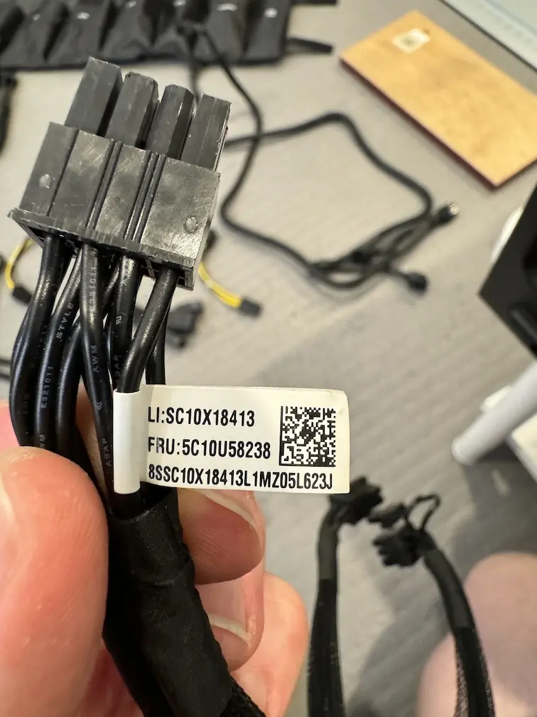
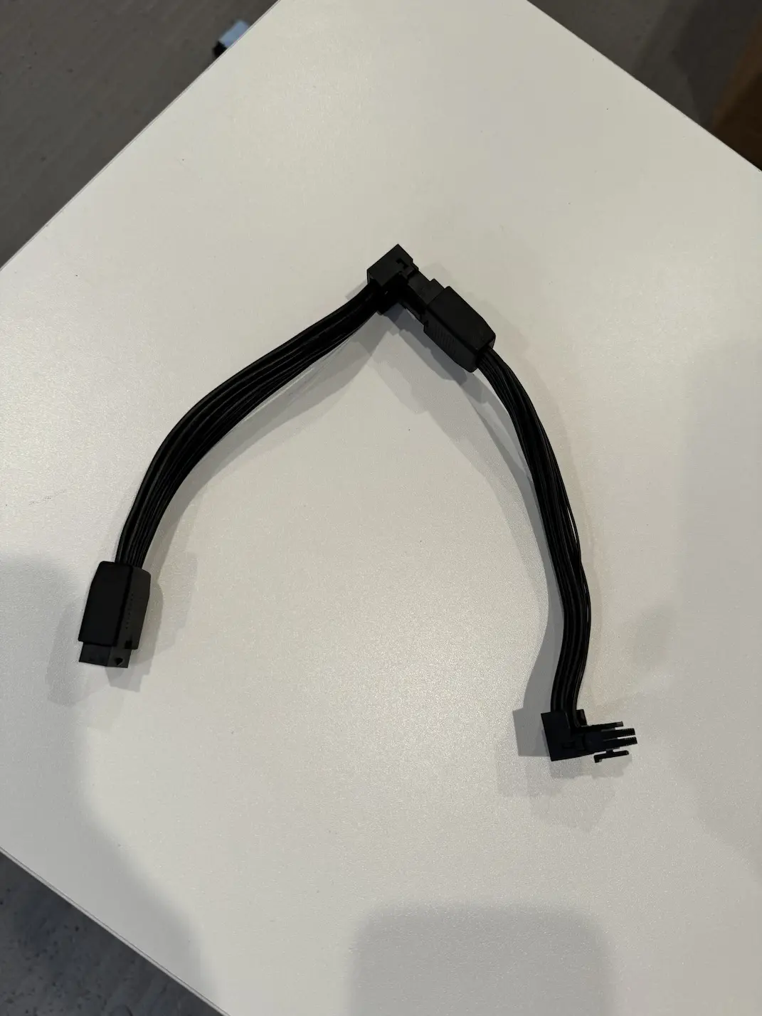
The GPU was already using a 12-pin 12VHPWR cable, but I had another spare one too (as I didn’t know which L-angle power cable would fit best for the limited space in the chassis). So I could chain them if needed, not perfect, but at least it wouldn’t be a roadblock for now.
Now it’s time to cut a hole!
However, I don’t have an angle grinder and I wouldn’t have used it then anyway, despite the urgency, as it was well beyond midnight by now.
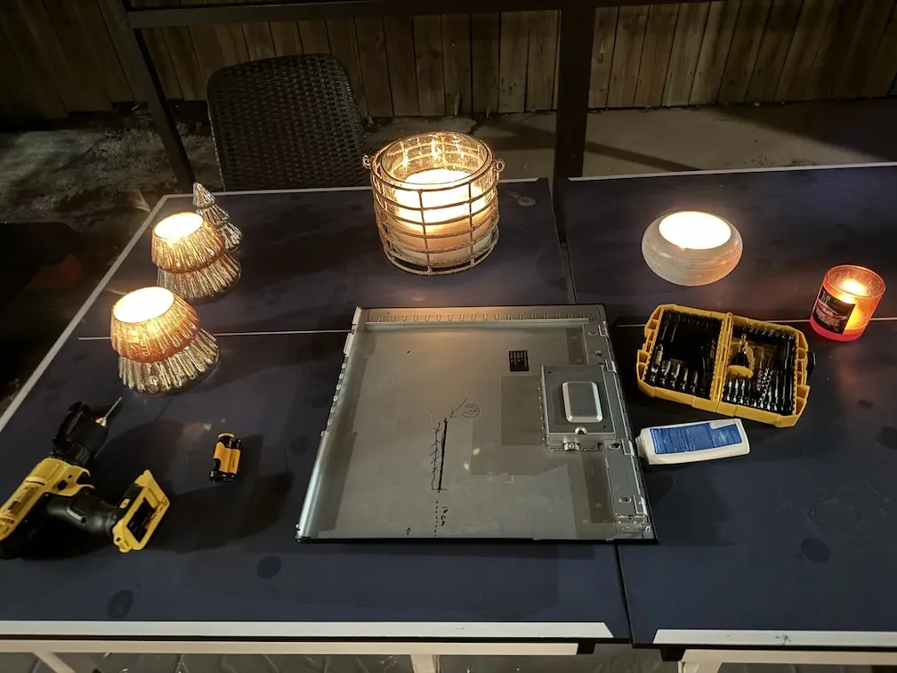
I did have a powerdrill though! No decent lighting at the outdoor ping-pong table in the middle of the night, so candles had to do. The little blue bottle on the right side was for simultaneous mosquito-fighting while completing my quest.
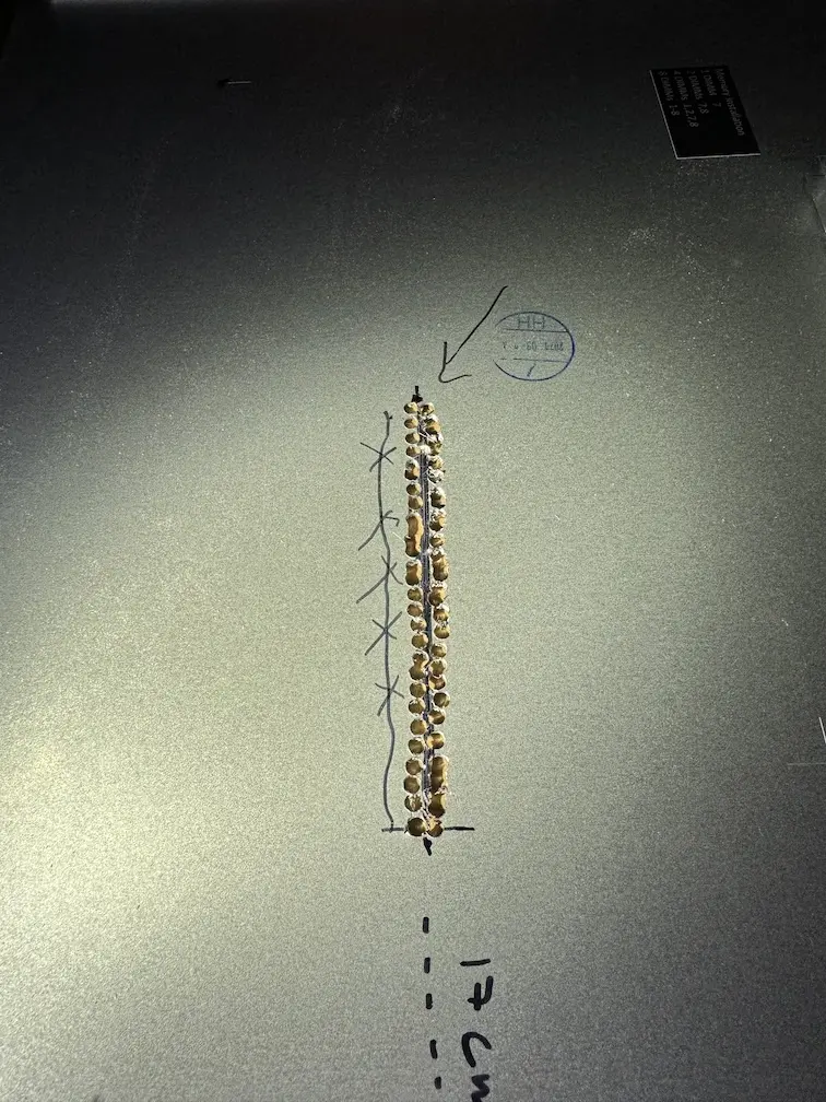
Since I did not have an angle grinder or anything more serious, I decided to divide and conquer - drill a lot of small holes and then combine them into a bigger one with whatever tool I can find next. Success!
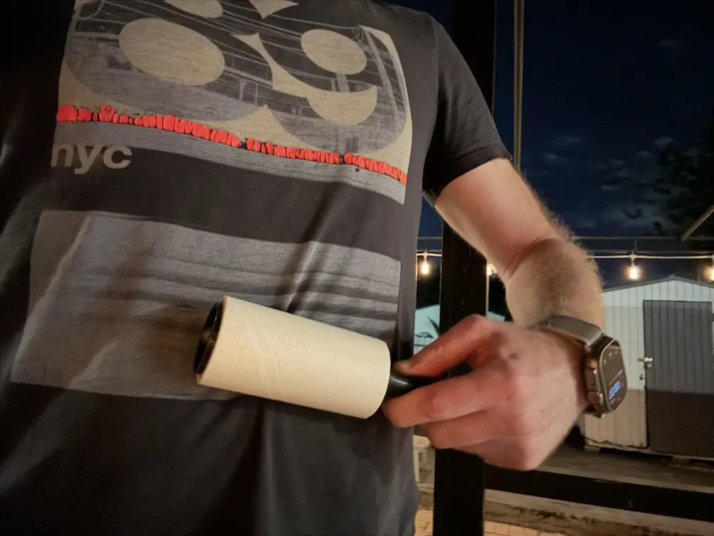
The reason I was doing this work outside is because I didn’t want any of the fine metal dust to end up in the house and in my servers or GPU! So I used a lint roller on my clothes before going inside. When back, it was time for phase two!
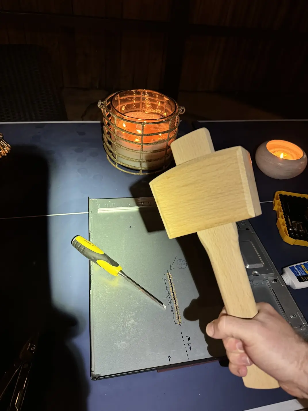
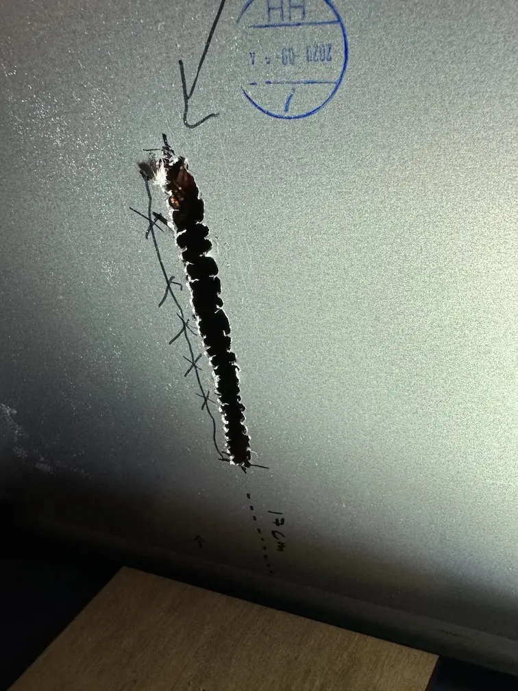
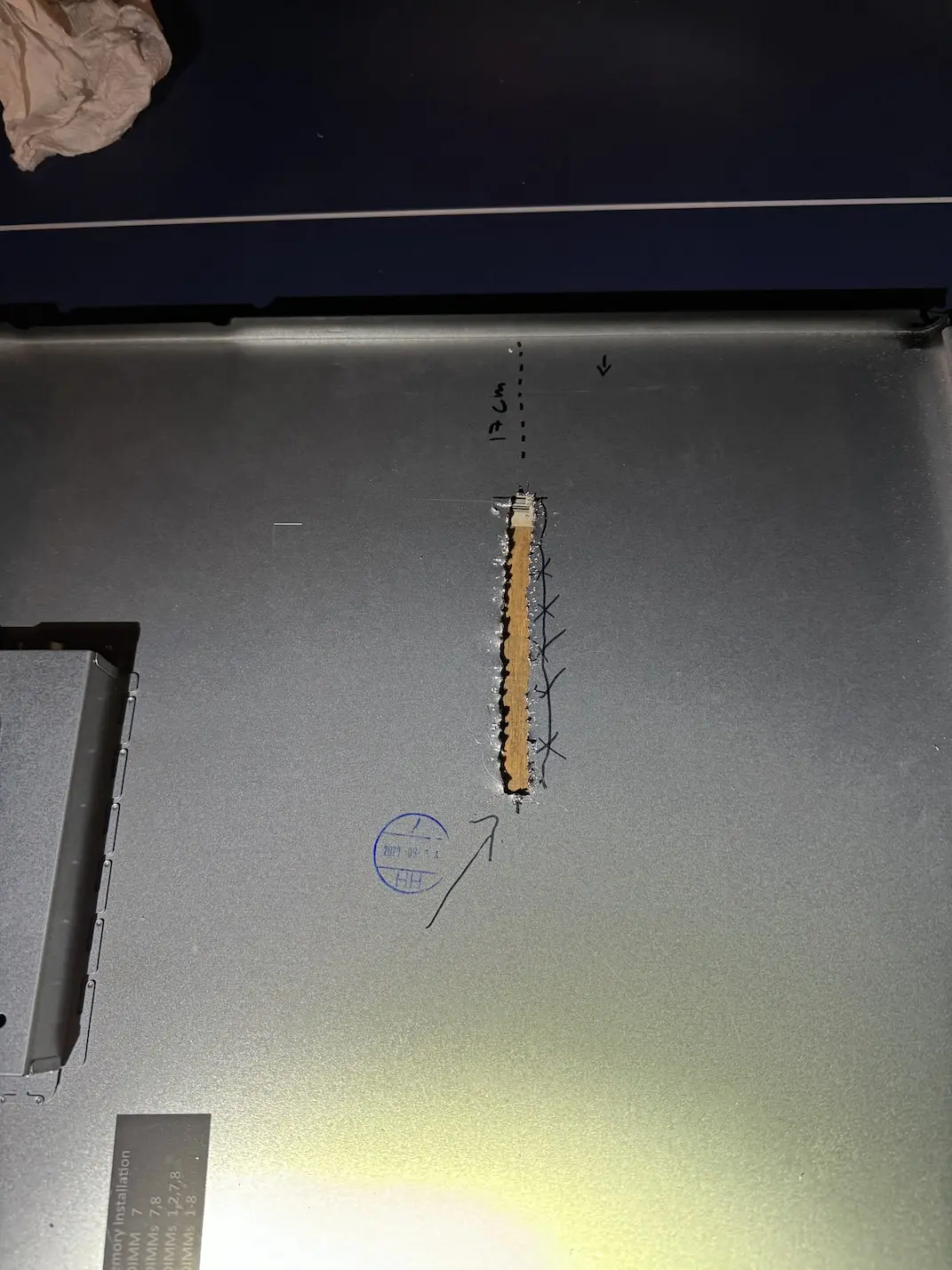
The best tools that I had available for this step were an unlucky wood chisel and a wooden hammer. I can finally put them into use! I was patient and tried to not make too much noise - and we have results! If you look into the image above on the right, that looks like the worlds most dangerous PCIe eGPU port!
As a side note, last year my wife asked me “why on the earth do you have a WOODEN hammer?”. Like I told her back then and am telling you now, I don’t necessarily remember the exact, particular, directly specific reason, but I do remember that there was a reason for buying it. And now you know.
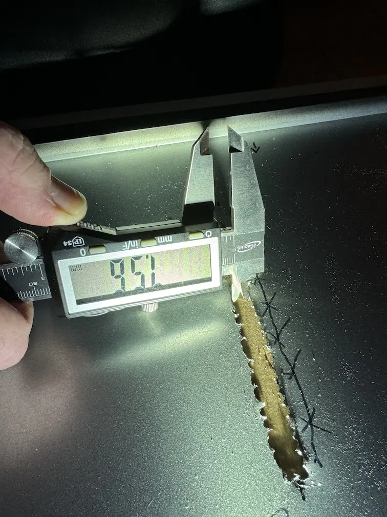
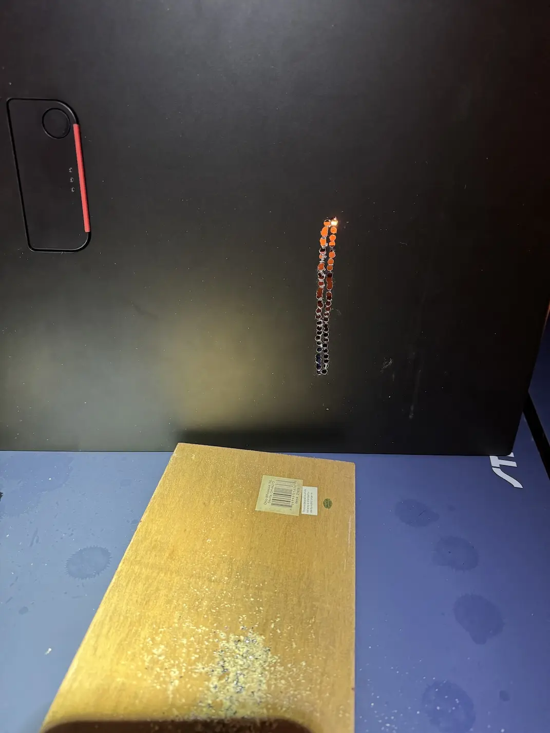
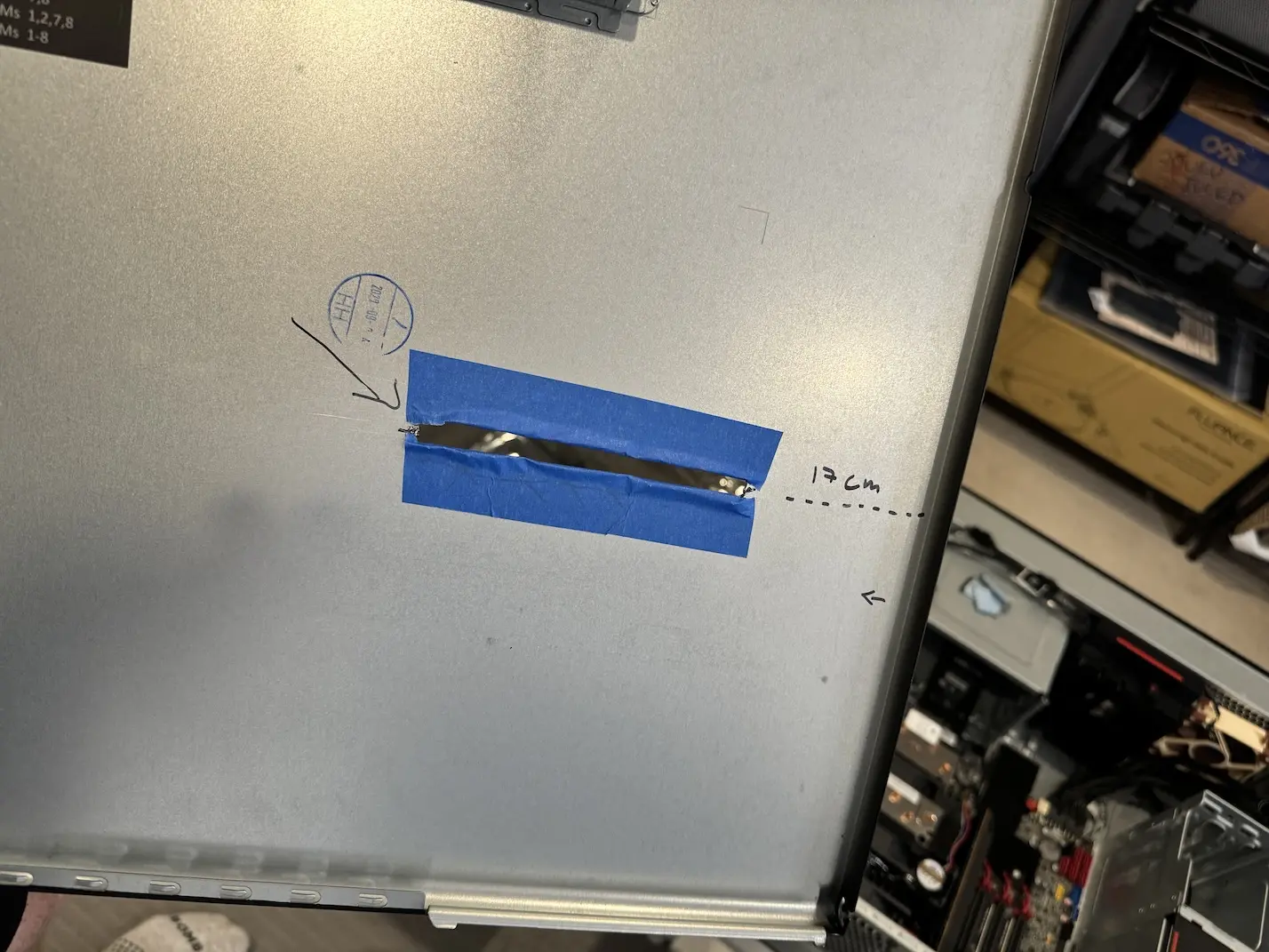
Ok, let’s verify if the plastic PCIe connector would fit through the hole - success! The unit of the width measurement (7.56) is in millimeters.2
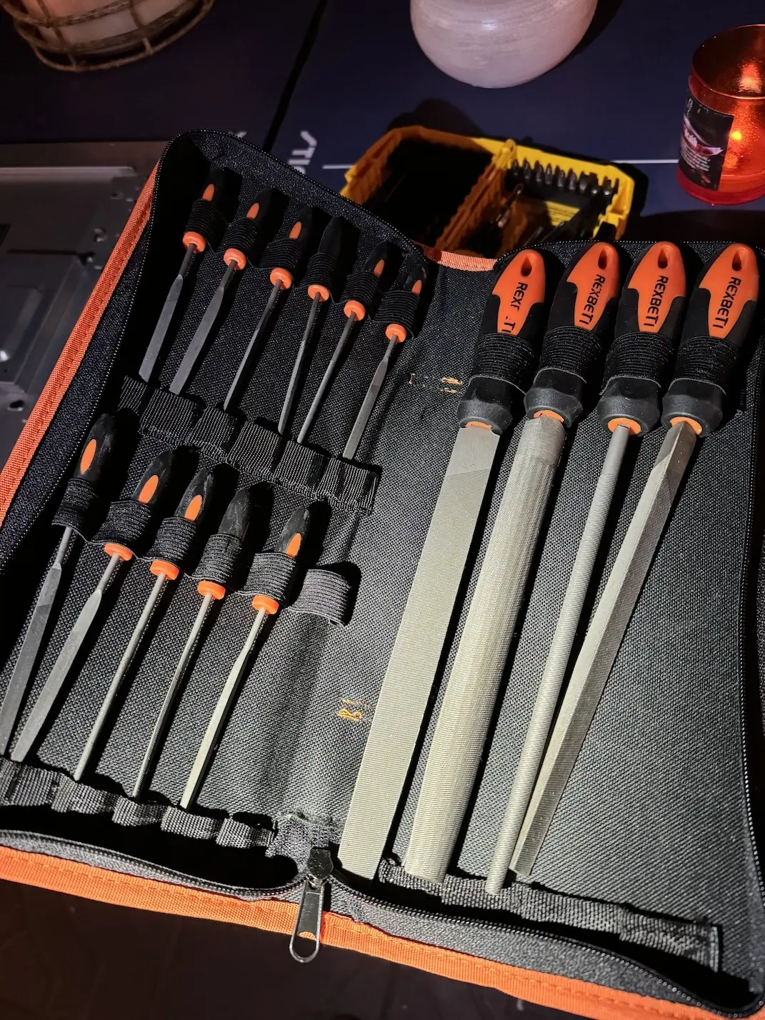
Next I had to make the opening a little less dangerous with a file. I’ve had this set of files for years, for the reason of scratchiness of an aluminum gate at my previous house. The end result, at least there are no sharp spikes leaning out anymore, good to go for the next step.
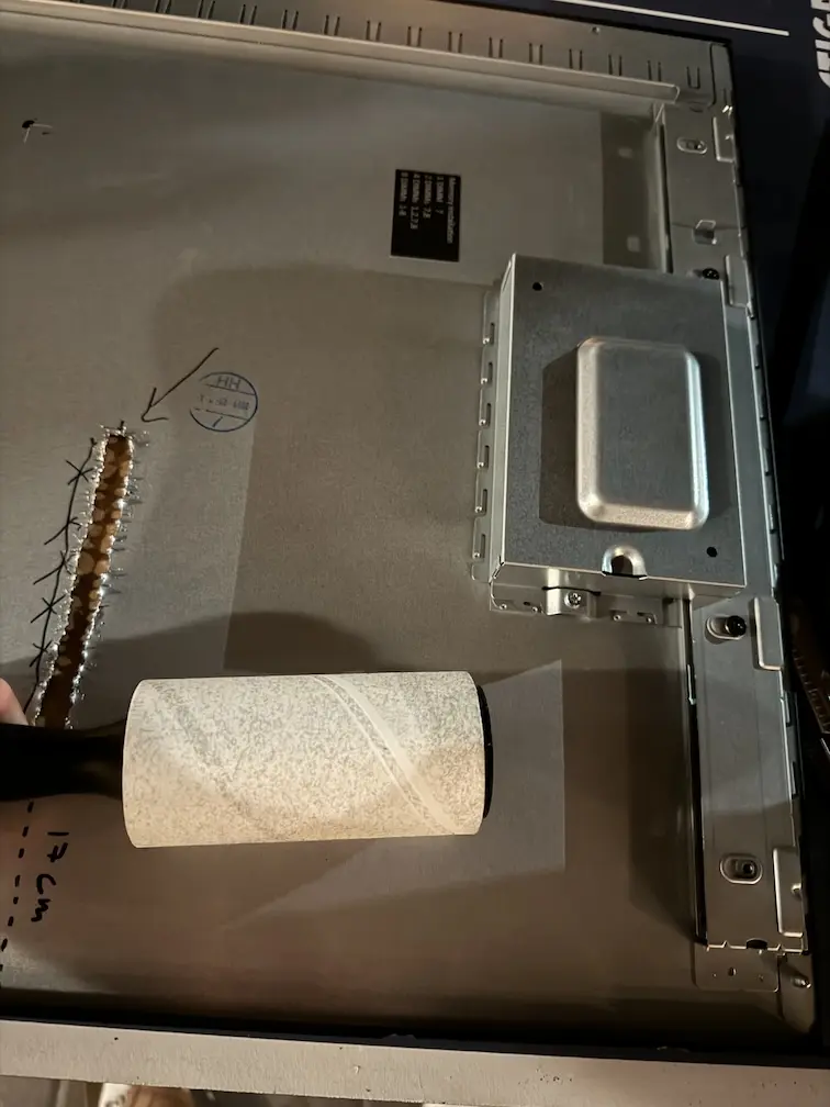
Before taking the panel back indoors, I wiped the panel clean from the larger metal particles and used a lint roller to hopefully catch smaller ones.
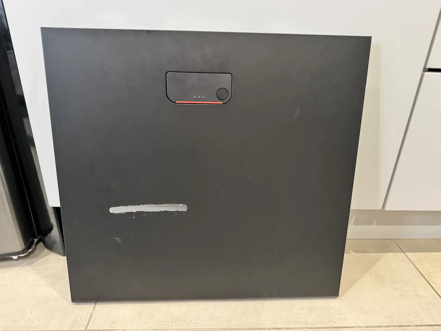
The result, indoors and with some electric tape added. Time to start assembling this thing!
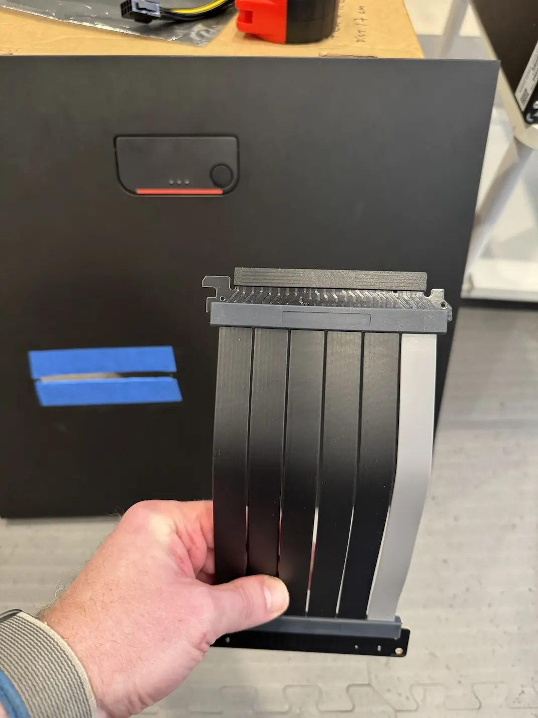
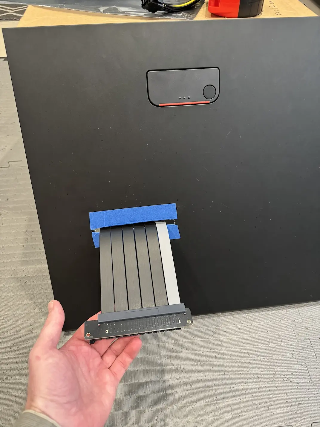
The PCIe riser cable nicely fits through the new eGPU port. Now it’s time to add all the other desired PCIe cards and close the chassis. There’s one unused PCIe slot between other cards, for the GPU riser cable.
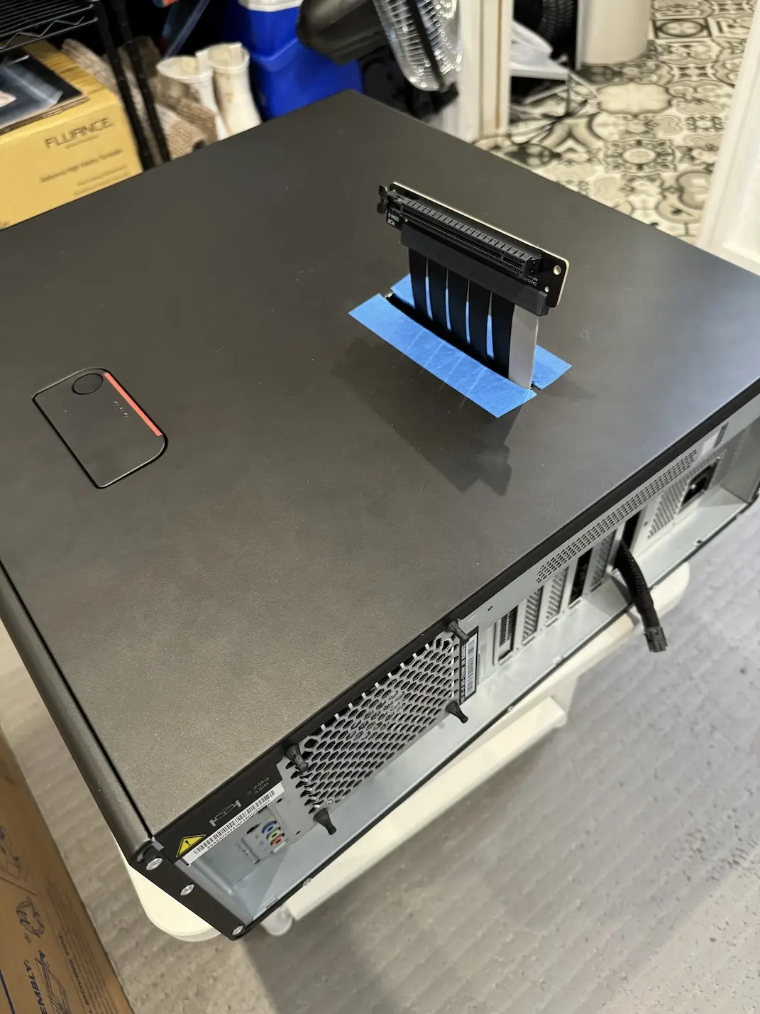
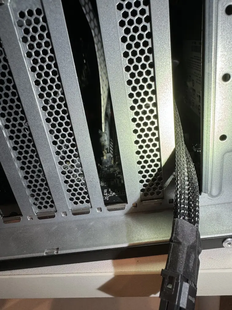
The PCIe riser cable goes through the hole I made to the side panel and the GPU power cable just goes through a PCI card slot opening in the back of the chassis. I initially thought that I’d have to drill a hole for the power cable too, but since I could chain 2 power cables, the less noisy way was to just use one of the PCIe card openings.
Since the PCIe riser cable is not that long, pushing the cable’s PCIe connector properly to its slot was somewhat challenging as you can’t access the area with your hands once the side panel is closed. I’m not particularly proud of this clumsy physical hacking step, but after a few tries with a long screwdriver and some mild cursing, I made it work!
Ok, how do we place the newly converted eGPU on the chassis so it would not stress the PCIe riser cable or fall over?
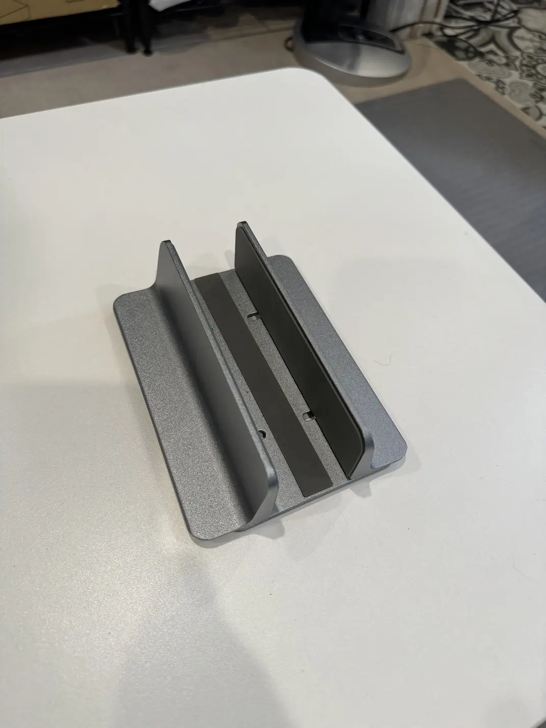
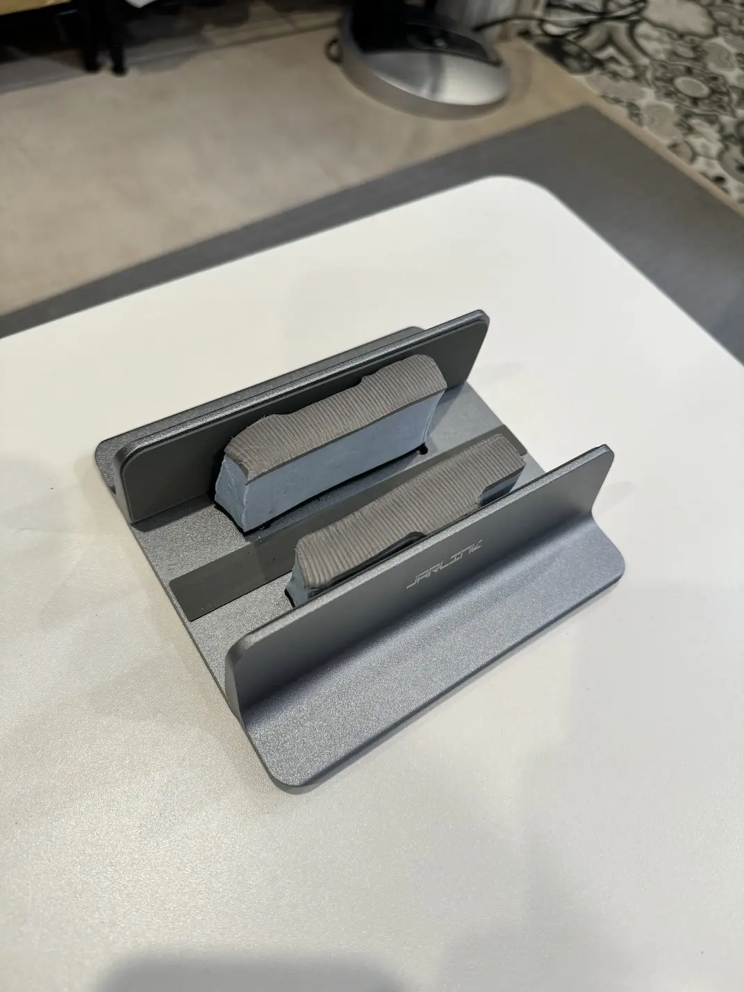
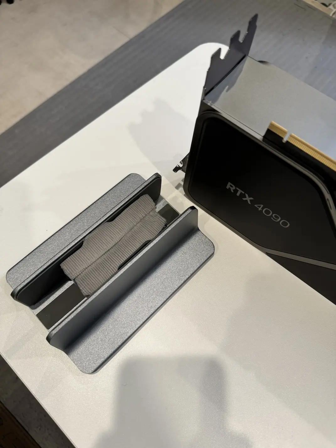
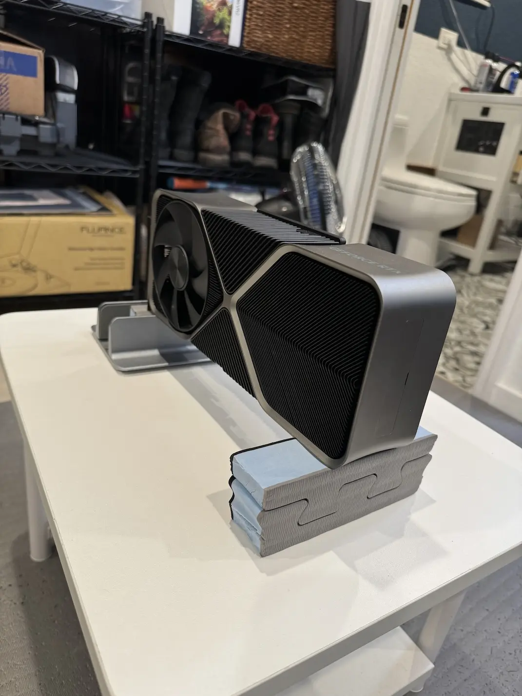
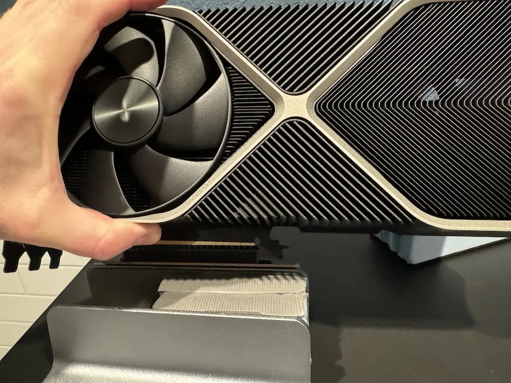
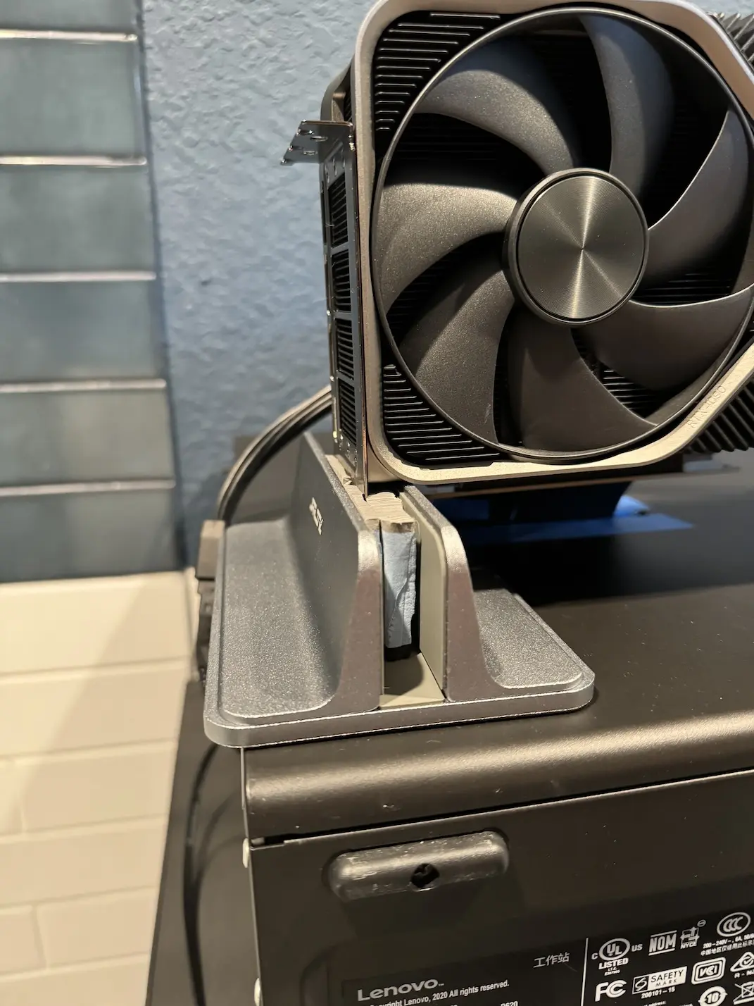
I did have a random laptop “clamshell-mode” stand around for some reason (never actually used it until now). So, I could just place the front of the GPU (that has the HDMI/DP outputs) on that. It required some padding though as the laptop stand was meant for wider things. Luckily I have plenty of my 5-year old exercise mat tile components around that I have used for fixing or supporting many other things at my household by now.
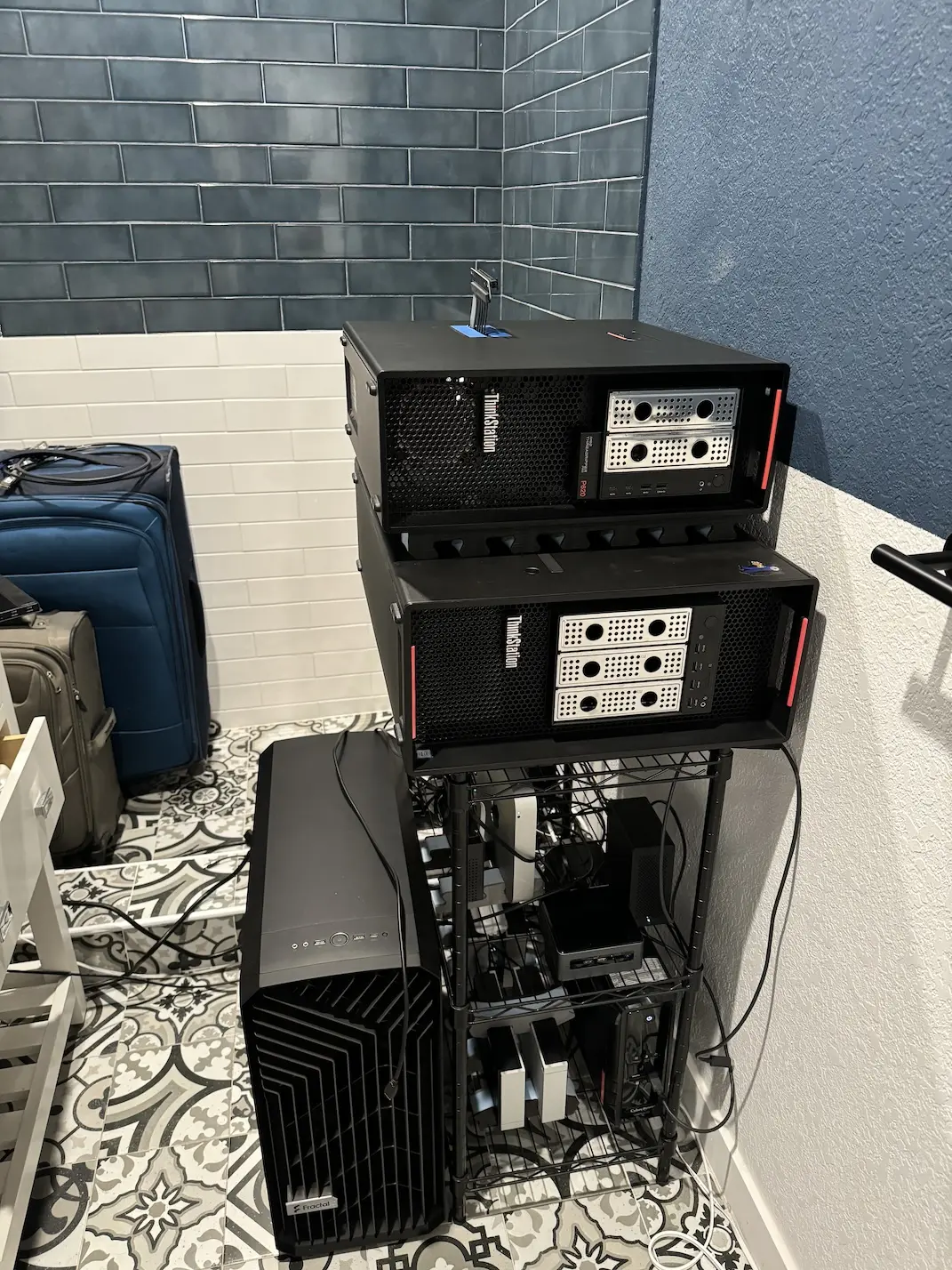
Now it’s time to see how it would work for the GPU (and yes, my private cloud is in the crapper).
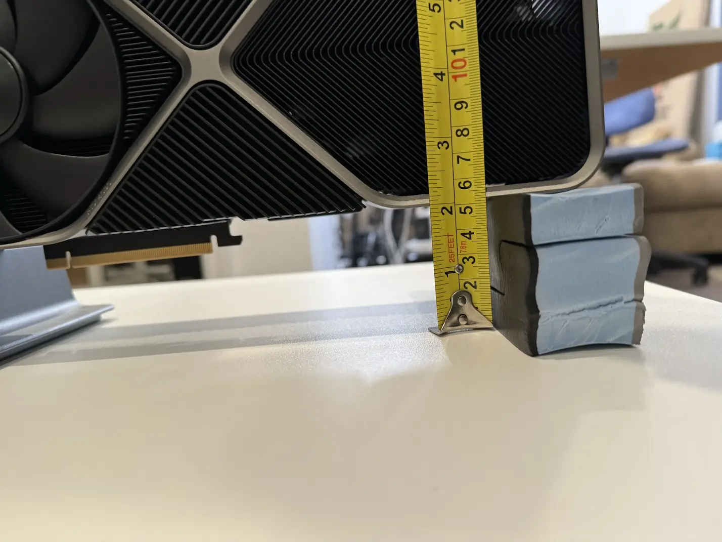
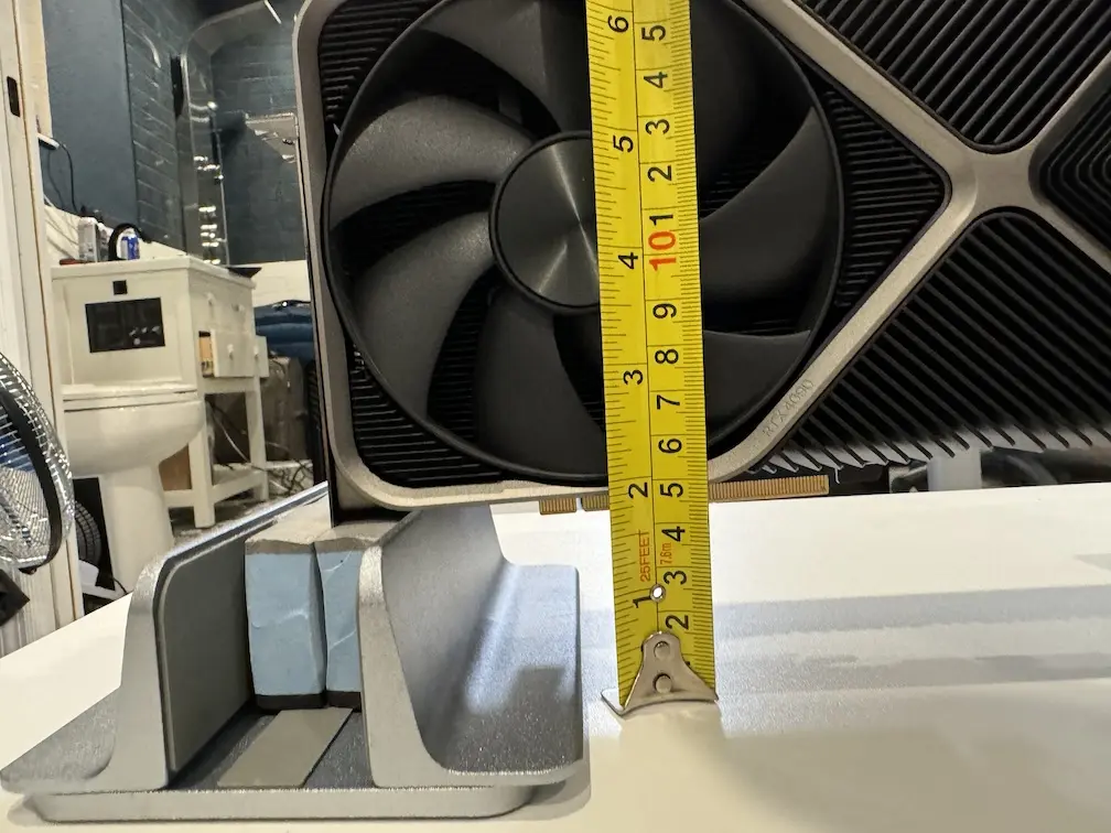
I used the excercise mat components to support both ends of the GPU. To anyone who noticed: I did lift one end of the GPU by 1mm in the final setup so that both sides would be at an equal height and I could sleep well.
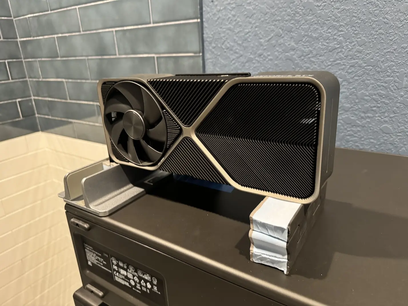
Ok, this is the setup, unconnected.
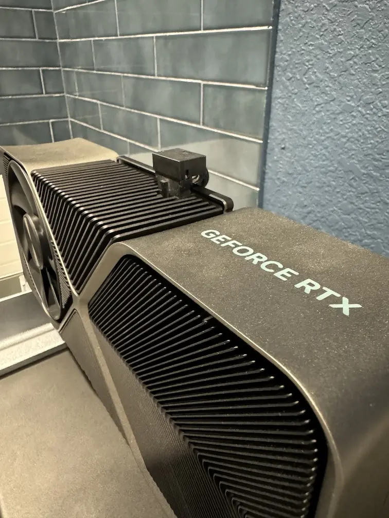
This is the setup, connected!
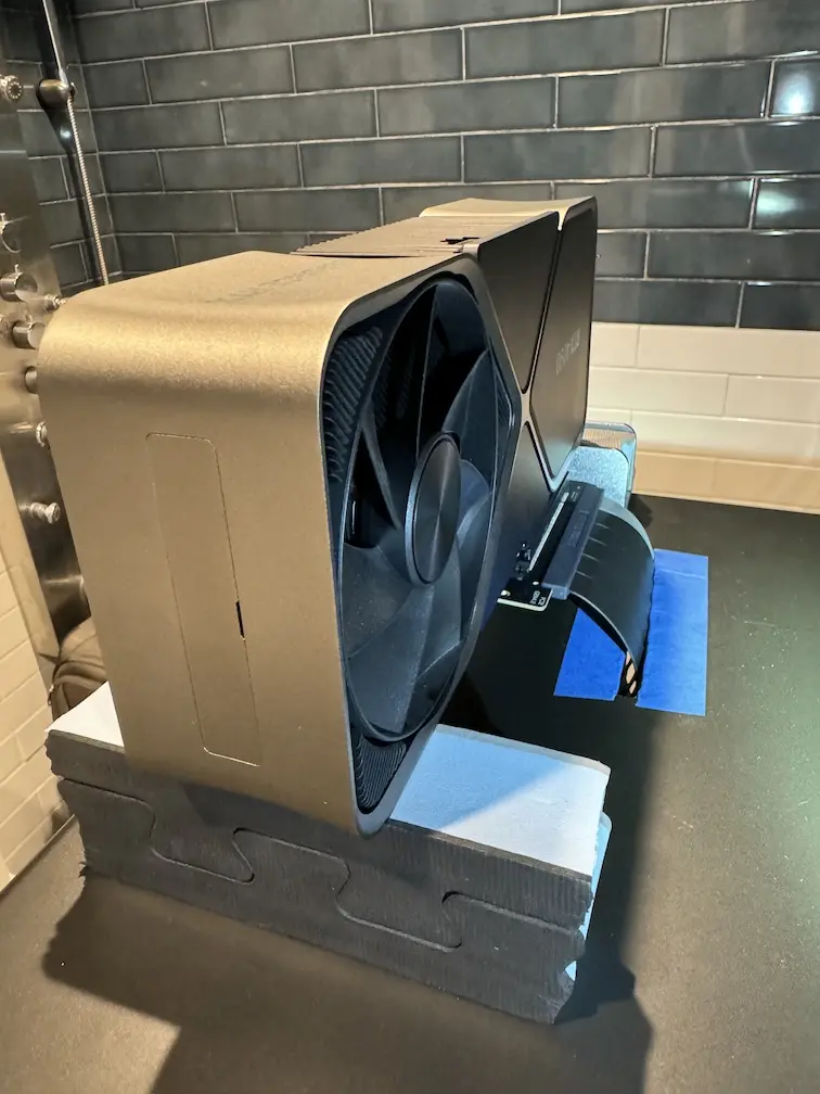
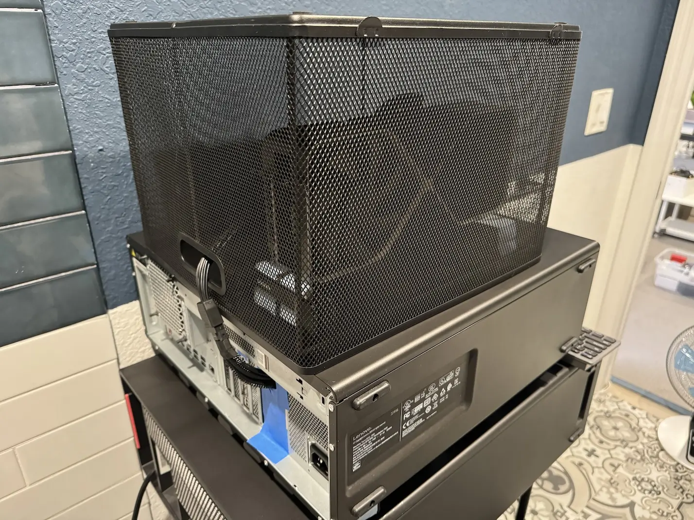
Now, I didn’t want my hair to accidentally get ripped out by the GPU fans (or even worse, to damage the GPU!), so I needed to come up with an eGPU enclosure with a solid airflow rating (at 3am)!
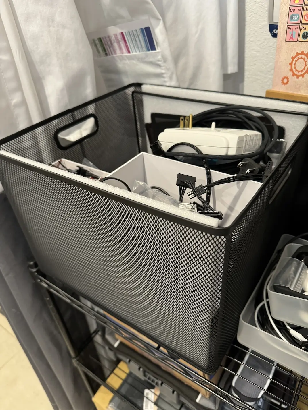
I didn’t have to look far, I spotted my goto useful box of junk (not useful junk, useful box of junk!), this should work perfectly and it’s even color-matched for additional satisfaction!
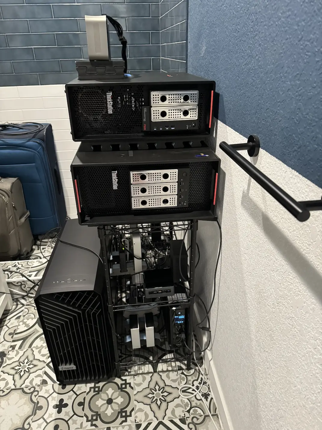
The End Result
So now we can do this:

Before and after.
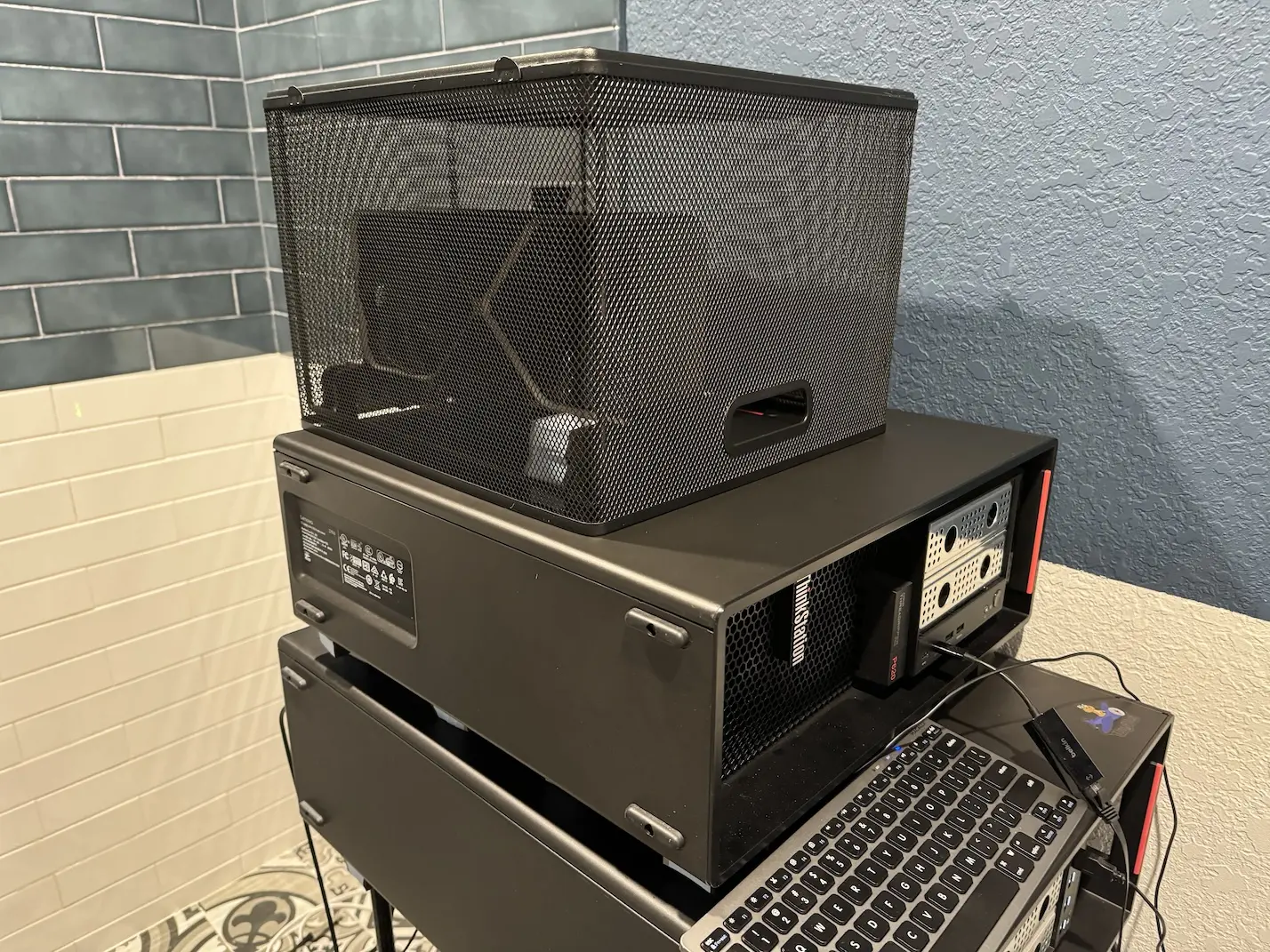
More angles to admire.
But let’s turn this thing on and run stuff on it!

And it worked! No cooling issues whatsoever, not for the GPU nor any of the other internal PCIe cards, despite the occasional ominous 666W power draw reported by my UPS when under load.
I was mildly concerned about whether the PCIe extender cable actually worked and if I would start seeing regular PCI AER errors or throughput issues, but for the last 5 months, no problems!
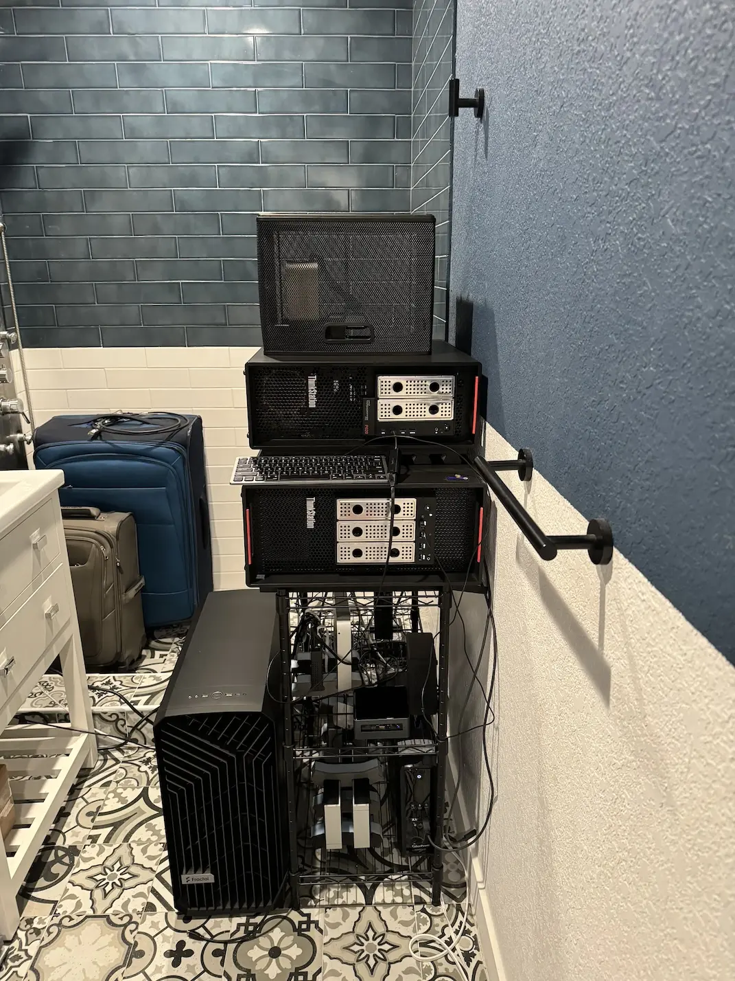
So, overnight, I went from this (left image above) to that (right image) and can do both GPU stuff and ridiculous I/O at the same time, without always having to investigate. Time well spent indeed!
Here’s a YouTube video of me turning this thing on the first time (plus other computer geekery in the channel):
Lessons Learned
- Keeping old cables around will pay off big time someday (just HODL until the big revelation)
- If you’re gonna have a box of junk, make sure the box is sturdy and versatile (and a nice color)
- You never know when you’d need a wooden hammer, so better get one now
-
https://download.lenovo.com/pccbbs/thinkcentre_pdf/ts_p620_power_configurator_v1.4.pdf ↩︎
-
Editor’s note: 7.5 mm is about as wide as seven and half of one millimeter diameter spaghettis placed side-by-side! ↩︎